Earthing systems – correct implementation, documentation, and compliance with standards
An earthing system is designed to create an electrical connection to the ground surrounding a building or an installation. Often, it is a requirement that an electrical installation has an earthing system with a specified transition resistance to neutral earth. At Electricon, we are experts in designing and installing earthing systems.
An earthing system can be designed in various ways, and the most common types of earthing systems are the following:
- Earth rods
- Foundation earthing
- Ring earthing or earthing grid
Regardless of the type of earthing, Electricon has developed a specialized concept that ensures the earthing system complies with all applicable standards – and continuous process control and final documentation are prepared for the installation.
All earthing systems are delivered with a measurement report documenting the system design and the final transition resistance to neutral earth.
Types of earthing systems
Earth rods
An earth rod is an earth electrode that is driven into the ground – often also referred to as a deep electrode. For smaller installations, an earth rod can be used as the primary earthing system, but it must always be connected to the installation’s protective equipotential bonding. The advantage of a deep electrode is that the transition resistance remains stable throughout the year, regardless of soil moisture.
The transition resistance of an earth rod can be calculated based on the length of the electrode and the electrical conductivity of the soil. If the conductivity is known, the required length of the electrode can therefore be predicted.
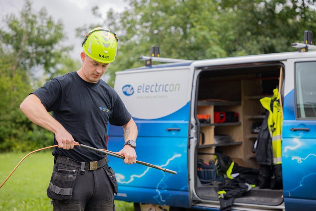
A standard earth rod from Electricon is constructed with a continuous copper conductor that is driven into the ground by a steel rod, which is installed using an electric or hydraulic hammer. This principle ensures that the electrode can be driven to a considerable depth – thereby achieving a low transition resistance – and also provides a very long service life, as any corrosion will first affect the steel rod before the copper conductor.
In larger earthing systems, for example for large transformer stations and/or lightning protection systems, earth rods are used as a supplement to foundation earthing, ring earthing, or earthing grids. Often, one or more earth rods are installed at each down conductor of a lightning protection system and connected to the ring electrode and the foundation electrode.
Where earth conductors are laid out as part of an earthing grid in terrain, the installation is often terminated with a deep earthing electrode at the end of a radial, or at a natural corner of the earthing grid.
An earth rod in a lightning protection system can usually not stand alone. Due to potentially very high step voltages around the electrode, it must always be combined with a ring electrode or an earthing grid.
Foundation electrode
A highly effective earthing system is achieved by incorporating the metallic reinforcement in a concrete foundation beneath a building or installation. There are clear and relatively simple guidelines for how a foundation earthing system must be constructed in order to be used as an earth electrode for an electrical installation.
A foundation earthing system is not automatically the same as the requirement under DS/HD 60364-4-41 to carry out protective equipotential bonding by connecting accessible reinforcement in reinforced concrete structures.
Conversely, if the guidelines for establishing a foundation earthing system are followed and it is properly connected to the main earthing bar and the main equipotential bonding bar, the requirements for protective equipotential bonding will be fully met.
Fundamentally, a decision must be made as to whether the foundation earthing system is to be used for lightning protection or solely as an earthing system for an electrical installation. If it is for lightning protection, the system must be designed in accordance with DS/EN 62305-3, and if it is only for a standard electrical installation, it must be carried out in accordance with DS/HD 60364.
Basically, the foundation electrode consists of a perimeter conductor in the outer edge foundation and in significant strip foundations. In basement slabs, or where the ground slab has direct contact with the soil, a mesh grid must be established in these slabs to ensure that the entire slab forms an integrated part of the foundation electrode. In all column foundations, an electrode must likewise be installed and connected to the mesh grid in the slab or to the perimeter conductor.
Depending on which standard the system is designed according to, the requirements for conductor cross-sections in the electrode and the size of the mesh grid to be established in the ground slab will vary. All point foundations for columns in the building must be included in the electrode, regardless of which standard is applied.
The next question is whether the foundation actually has contact with the surrounding soil, or whether it is insulated or made watertight, which may result in the foundation not being fully electrically connected to the ground. An insulated or watertight foundation cannot be expected to have a sufficiently low transition resistance.
If this is the case, the standards require that an earthing grid be established beneath the ground slab—on the outside of the insulation or waterproof membrane. This external mesh grid must be installed whether it is for lightning protection or simply as a foundation electrode for an electrical system. Depending on the standard, the requirements for the dimensions of the mesh grid will vary.
Even if an external earthing grid is installed, the same requirements still apply for the construction of the perimeter conductor and internal mesh grid, as well as the earthing of column foundations within the foundation itself.
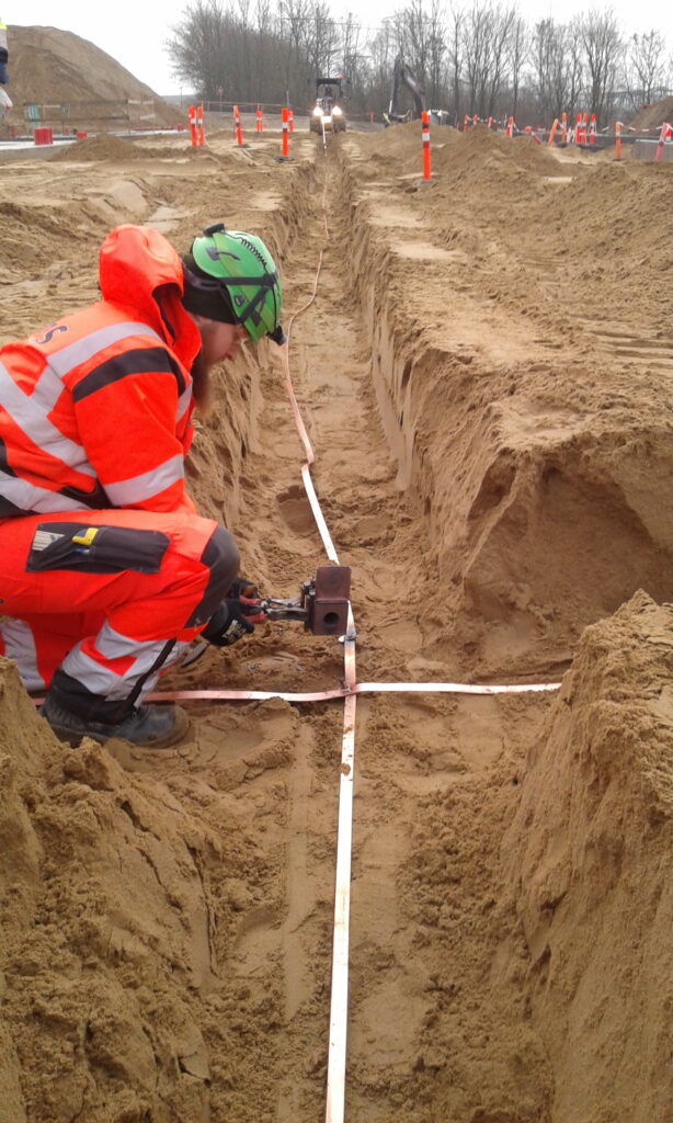
Ring earthing or earthing grid
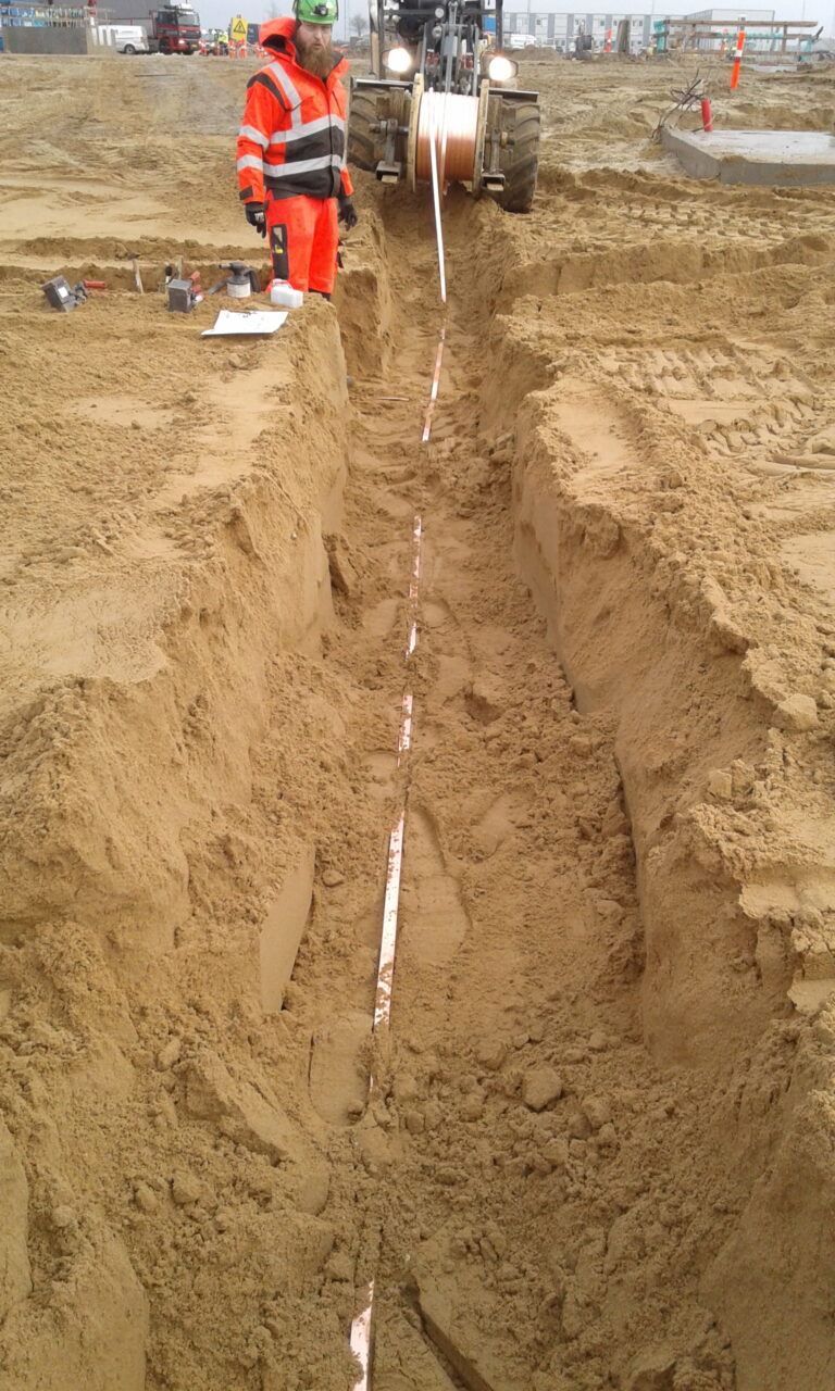
A ring earthing system or an earthing grid is an extensive earthing system established in the terrain around a building or between several buildings and outdoor installations. The purpose of an earthing grid is to ensure that all buildings and installation components reference the same earth potential, so that no dangerous voltage differences arise between components in the event of faults, short circuits, or lightning strikes in the system.
The earthing grid is constructed using buried bare copper conductors with a sufficient cross-section to carry the currents that will flow in the earthing system. Connections within the earthing system are made using either high-pressure crimped or welded joints.
Important information
Common to all earthing systems is that they must create the best possible connection to the surrounding ground. This is measured as electrical resistance (ohms).
The term impedance refers to the electrical resistance that occurs in connection with alternating current, such as transients. Low impedance at high frequency is a prerequisite for effective dissipation of, for example, lightning strikes. In general, the resistance should be as low as possible. Various regulations specify maximum values that the resistance/impedance must remain below.
In practice, 0 ohms is impossible to achieve, and there will therefore always be a balance between purpose and cost in each individual case.
The choice of the right solution also depends on the practical possibilities at the site.
In order for an earthing system to meet the functional requirements, Electricon ensures that all applicable standards are met as a minimum.
Our many years of experience also mean that we know how to maintain functionality even after many years of operation.
Already in the advisory and design phase, we build in operational reliability and sound long-term economics. In addition to being able to document that an earthing system functions as intended, we can also ensure that the system will operate correctly for many years.
An earthing system that is not correctly dimensioned or that is executed with faults will be very costly and, in some cases, impossible to correct once construction is completed.
During planning and execution, we assess whether surface electrodes or deep electrodes should primarily be installed. We take into account the conductivity of the subsoil, the amount of space available for the system, whether the work is carried out in connection with new construction on raw ground, or whether there are surfaces such as stone paving or asphalt.
Earthing electrodes must be installed at a depth that ensures that drying out and frost do not cause the transition resistance to earth to exceed the prescribed value. Electricon ensures this by installing deep electrodes with an uninterrupted copper conductor.
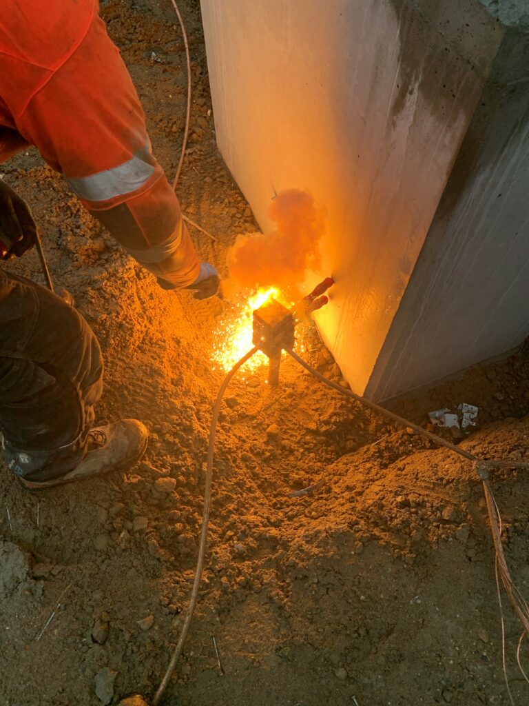
Joints are carried out according to best practice principles, including exothermic welding and special connectors that prevent galvanic corrosion.
Electricon uses only the best materials, including noble metals for electrodes and penetrations. We collaborate with leading manufacturers in Europe, giving us constant access to the latest and best products on the market.
We are ready to help

A glimpse into our everyday life at Electricon

What our customers say
"Electricon carried out repairs on the existing lightning protection system at Gråsten Castle. The project was completed with Electricon serving as the main contractor...."
"Bravida can give Electricon A/S the highest recommendations for both quality and safety...."
"M. J. Eriksson A/S has been extremely satisfied with the service provided by Electricon. With an incredibly solution-oriented approach, everything has been delivered on time and within budget...."
"Electricon has been professional, adaptable, and service-minded throughout the entire process...."
"Electricon is a pleasure to work with. They are flexible and adaptable, always willing to adjust in order to achieve a common goal...."